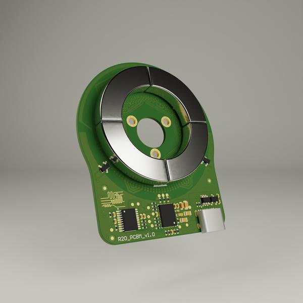
R20 PCB Motor
The goal of this project was to create a small, highly efficient, and extremely affordable PCB Motor. The “comb” design allows for greater efficiency and torque density.
The Comb PCB motor redefines what’s possible in accessible, efficient, and versatile motor solutions.
- USB-C Powered: Powered through a standard USB-C connection, making it incredibly user-friendly and compatible with modern power sources.
- Cost-Effective Manufacturing: Designed with simplicity and scalability in mind, it is extremely affordable to produce—perfect for hobbyists and large-scale applications alike.
- Efficient: The comb-shaped stator maximizes efficiency by eliminating torque loss, ensuring optimal performance even under demanding conditions.
- Seamless Integration: Fully customizable, the motor can be easily modified or directly integrated into any project requiring a compact, inexpensive motor solution.
- Advanced Control Capabilities: Built-in position, velocity, and torque control offer a level of precision and flexibility typically reserved for far more expensive systems.
In short, this PCB motor combines cutting-edge design with practicality, making it an ideal choice for engineers, makers, and innovators everywhere.
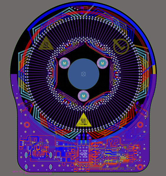
Layout
The Comb PCB Motor is built on a 4-layer PCB structure. The comb design ensures that the entire copper area under the magnets contributes to producing torque, increasing efficiency and torque density. A simple and efficient motor control circuit is integrated on the same PCB, including:
- Hall sensing for precise commutation and efficient low-speed operation.
- A microcontroller to allow advanced control actions like closed-loop position and velocity control.
- Full customizability of the layout allows tailoring the motor’s target speed, torque, and operating voltage/current to each specific application.
Simulations
Before manufacturing any hardware, extensive simulations guided the design:
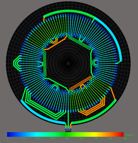
- PDN Simulation: Several iterations of PDN simulations were performed to optimize copper usage. The first iteration showed that the copper distribution was not optimal (red areas should be made thicker) and vias were carrying too much current.
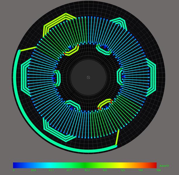
Doubling the number of vias and increasing the trace width of some critical parts showed promising results.
- Resistance and Current Handling: DC resistance was estimated from PDN results (770 mΩ predicted).

- FEMM Magnetic Simulations: FEMM was used to model the magnetic field experienced by the stator traces.
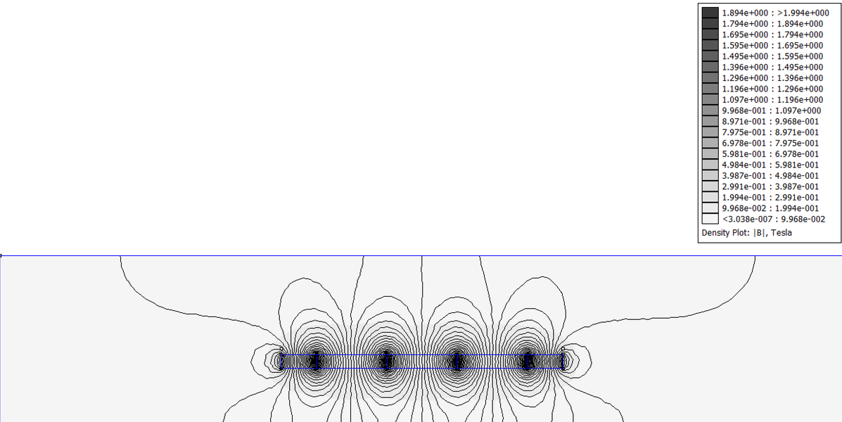
- Lorentz Force and Torque Simulations: FEMM data was imported into MATLAB, where Lorentz forces and resulting torque were computed.
Estimated constants:
- Kt: 1.48 mNm/A
- Kv: 6452 RPM/V
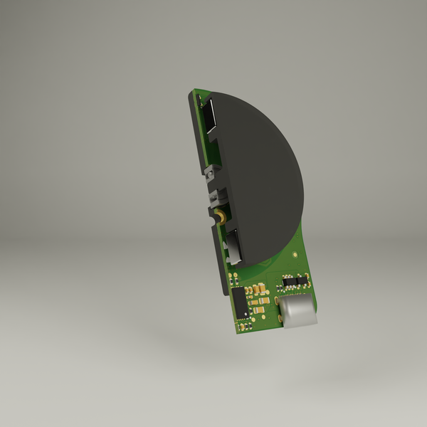
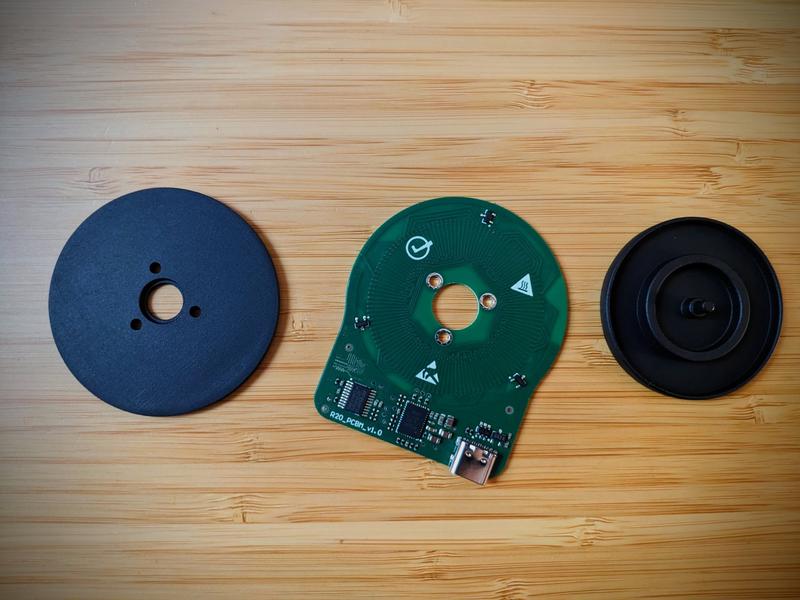
Mechanical Design
The mechanical structure is simple:
- Stator: The PCB itself.
- Bearing Holder: 3D printed and screws into the PCB.
- Rotor: 3D printed, holds the magnets and is press-fitted into the bearing.
Results
The PCBs and mechanical parts were received and assembled.
First tests revealed several lessons:
- Ferromagnetic Screws: Caused cogging torque; switched to stainless steel/CA glue.
- Bearing Play: Only one bearing caused axial play; future versions will use two.
- Hall Sensors: Two were swapped; corrected after rework.
These early tests confirmed the basic viability of the motor while pointing out mechanical details to refine in future versions.
Tests
Once manufactured, the motor was fully characterized to validate the design and simulation methods used.
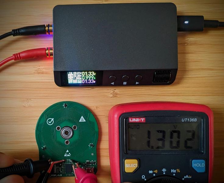
- Kv Test: 6450 RPM/V measured, very closely matching simulations. This positive result highlights how customizable a PCB motor can be.
- Resistance Test: 651 mΩ measured. A bit lower than simulated, this variation is expected due to final copper thickness variability of the PCB manufacturing process.
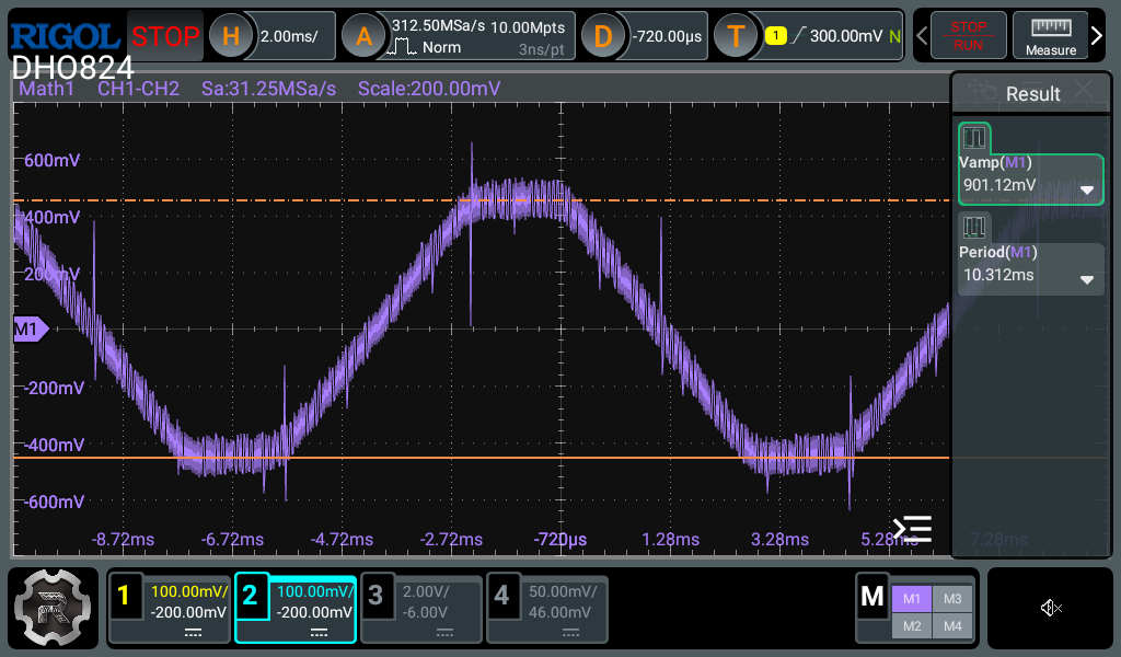
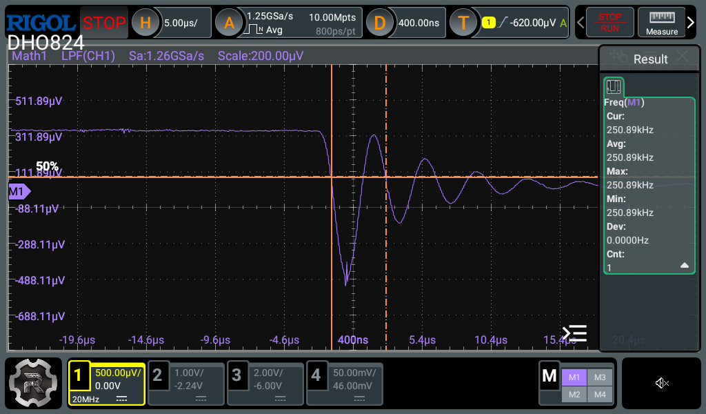
- Inductance Test: 2 µH measured. PCB motors are usually low inductance, and the driving circuit was designed to handle these characteristics without issue.
Control
The Comb PCB Motor includes basic yet powerful control modes made possible thanks to the integrated hall sensors and microcontroller.
- Velocity Control Mode: Closed-loop speed control. In this mode, the motor adjusts its drive signal based on feedback to match the desired speed, providing smooth and stable motion even under load changes.
- Position Control Mode: Simple closed-loop position control. The motor moves to and holds specified rotor positions, making it useful for robotics and actuator applications.
These control results demonstrate the strong capabilities of the design, paving the way for even more advanced closed-loop applications in the future.
Firmware
The firmware running on the motor is based on an STM32 microcontroller and was developed entirely from scratch. It performs several key tasks:
- Reading Hall Sensors: It continuously reads the hall sensor states to decode rotor position and estimate motor speed.
- Commutation and Control: Based on the decoded position, the MCU manages commutation patterns and applies control laws.
- Power Stage Interface: It communicates with the power stage IC through gate control signals and SPI communication.
- Closed-Loop Control: Both speed and position loops are closed at 1 kHz update rate, enabling smooth dynamic response and precision actuation.